222222222222222222.png)
About the product
High-voltage withstand testing of electrical equipment is one of the most important items specified in insulation preventive testing.
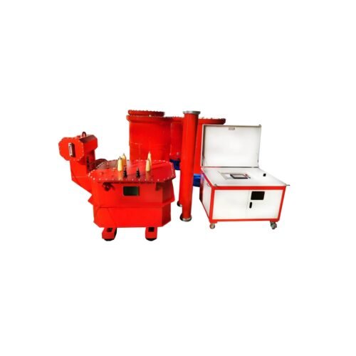
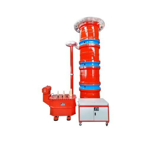
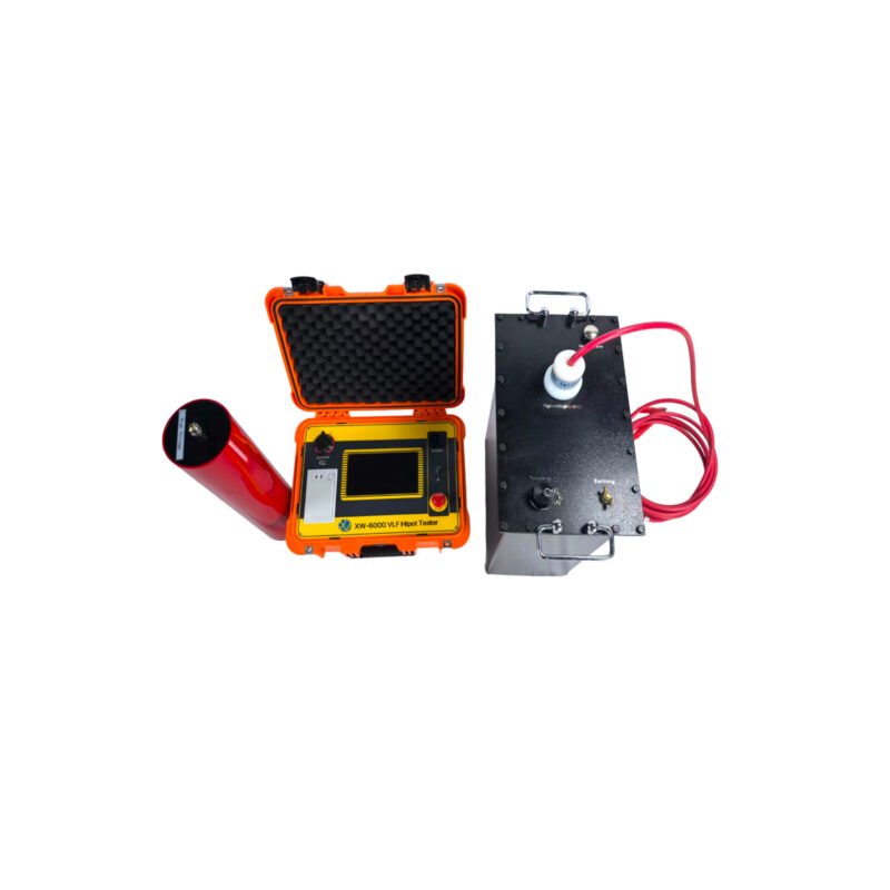
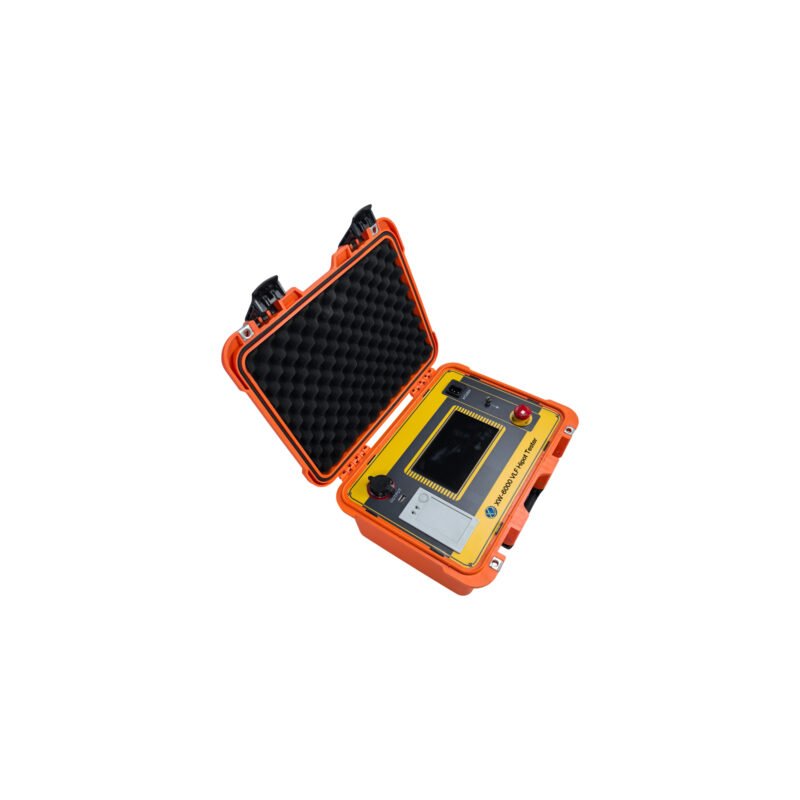
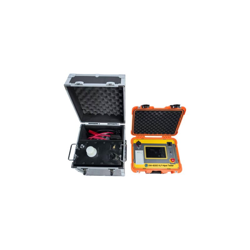
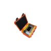
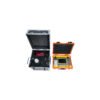
The withstand voltage test can be divided into AC and DC withstand voltage tests. The AC withstand voltage test can be divided into power frequency, frequency conversion, and 0.1hz ultra-low frequency test technology, of which 0.1hz ultra-low frequency technology is the latest technology recommended by the current International Electrotechnical Commission. Our company’s new generation of ultra-low frequency and high voltage generator is the core product independently developed with the latest American technology. It adopts a 7-inch touch screen, the latest ARM7 single-chip microcomputer, a high-speed data acquisition circuit, and is equipped with background management software. It overcomes many shortcomings of domestic similar products (see Table 1), and its cost performance is much higher than that of similar imported products. It is especially suitable for withstand voltage testing of electrical equipment with large insulation equivalent capacitance (such as power cables, power capacitors, large and medium-sized generators and motors, etc.), which conforms to the national standard of the electric power industry, general technical conditions for ultra-low frequency and High-Voltage Generators (d), newly issued in 2004 l / t849.4-2004.
| 0.1Hz Voltage-withstand equipment type | HV control method | High voltage waveform | Energy saving | Noise | Lifespan | Electrical life |
| mechanical | HV mechanical switch switching polarity | Square wave | Not energy-saving: consumes excess energy with high- power resistors | High | short | Short |
| Electronic | HV electronic switch switching polarity | Sine wave | Energy saving: feeds back excess power to the grid | A little | No lifespan, can use long- term | Long |
Table 1 performance comparison between mechanical type and electronic type of 0.1Hz voltage withstand test equipment
1. Advantages of 0.1Hz ultra-low frequency withstand voltage technology
In fact, the ultra-low frequency insulation withstand voltage test is an alternative to the power frequency withstand voltage test. In the power frequency withstand voltage test of large and medium-sized generators, motors, power cables, and other test objects, due to their large capacitance in the insulation layer, a large-capacity test transformer or resonance transformer is required. Some of this huge equipment is not only heavy and expensive, but also inconvenient to use. In order to solve this contradiction, the method of reducing the test frequency and the capacity of the test power supply is widely used in the world. It has been proved from many years of theory and practice at home and abroad that replacing the power frequency withstand voltage test with a 0.1 Hz ultra-low frequency withstand voltage test can not only have the same equivalence, but also greatly reduce the volume and weight of the equipment; theoretically, the capacity is about one fifth of the power frequency, and the operation is simple. This is the main reason why this method is widely used in developed countries.
According to the actual situation of China’s power system, the National Development and Reform Commission has formulated the industry standard of ultra-low frequency (0.1Hz) withstand voltage test method for 35kV and below XLPE insulated power cables. In 2004, the industry standard DL / T 849.4-2004, General Technical Conditions for ultra-low frequency and high voltage generators, was promoted in China. Although the DC voltage withstand test equipment has the advantages of small size, light weight, and low cost, the DC voltage withstand test is also the most destructive to the insulation of the tested object. (see Table 2) Therefore, the latest national regulations on preventive test of electrical equipment have expressly stipulated that DC high voltage is no longer used for voltage withstand test of electrical equipment, and AC voltage withstand test is recommended.
The new generation of 0.1Hz ultra-low frequency high voltage generator developed by our company adopts the latest power electronic components and the latest ARM7 single-chip technology, further reducing the volume and weight of the equipment, enabling full operation, more stable performance, overcoming the shortcomings of the first generation of mechanical booster, such as short service life, high failure rate, and large volume. Through years of practice, a large amount of user feedback shows that: – 80kV ultra-low frequency high voltage technology is leading in the country, with the highest cost performance!
Table 2: Performance comparison of various withstand voltage test equipment:
| Compare content | Power frequency withstand voltage | Frequency withstand voltage | 0.1Hz withstand voltage | DC withstand voltage |
| Equivalence | Good | Good | Good | Bad |
| Insulation destructive | Small | Small | Small | Big |
| Operation safety | Low | Low | High | A little low |
| Wiring | Complicated | Most Complicated | Most easy | Complicated |
| Volume and weight | Heavy and big | Heavy and big | Light and small size | Light and small size |
2.Technical parameters of series products
Ground voltage generator
| Model | Rated Voltage | Load | Fuse | Weight |
|
30KV /1.1 | 0.1Hz,≤1.1µF |
8A | ||
| 30kV | 0.05Hz,≤2.2µF | Controller:6Kg | ||
| (Peak Value) | ||||
| 0.02Hz,≤5.5µF | Booster:20Kg | |||
|
80KV/0.5 | 0.1Hz,≤1.1µF |
20A | ||
| 80kV | 0.05Hz,≤2.2µF | Controller:6Kg | ||
| (Peak Value) | ||||
| 0.02Hz,≤5.5µF | booster:50Kg |
1)Select products of appropriate specifications according to the subjects
When in use, the capacitance of the test object shall not exceed the rated capacitance of the instrument. If the capacitance of the test object is too small, the output waveform will be affected. If it is less than 0.05 μ F, the instrument will not output normally. At this time, a 0.05 μ f capacitor (provided by the company) can be connected in parallel for auxiliary output. See Table 4 and Table 5 for the estimation of capacitance of common electrical equipment.
Table 4 single-phase earth capacity of different types of generators.
| Steam turbine generator | Hydro generator | ||||||
| Capacity (MW) | 200 | 300 | 600 | 85 | 125- 150 | 300 | 400 |
| Single phase ground capacitance(uF) | 0.198 | 0.18- 0.26 | 0.31- 0.34 | 0.69 | 1.8-1.9 | 1.7-2.5 | 2.0-2.5 |
Table 5. Capacitance of XLPE-insulated single-core power cable (μ f / km)
| Voltage(KV) capacitance (uf/Km) Cross-sectional area (mm) | 16 | 25 | 35 | 50 | 70 | 95 | 120 | 150 | 185 | 240 |
| 10 | 0.15 | 0.17 | 0.18 | 0.19 | 0.21 | 0.24 | 0.26 | 0.28 | 0.32 | 0.38 |
| 35 | — | — | — | 0.11 | 0.12 | 0.13 | 0.14 | 0.15 | 0.16 | 0.17 |
2)Estimation method of test object current:
Calculation formula: I = 2 π FCU